Detailed Design and Engineering
Chapter 05 · Automotive Product Development
Use the infographic for the process overview, then follow the chapter sections for definitions, activities, deliverables, gate evidence, and implementation detail.
Chapter infographic
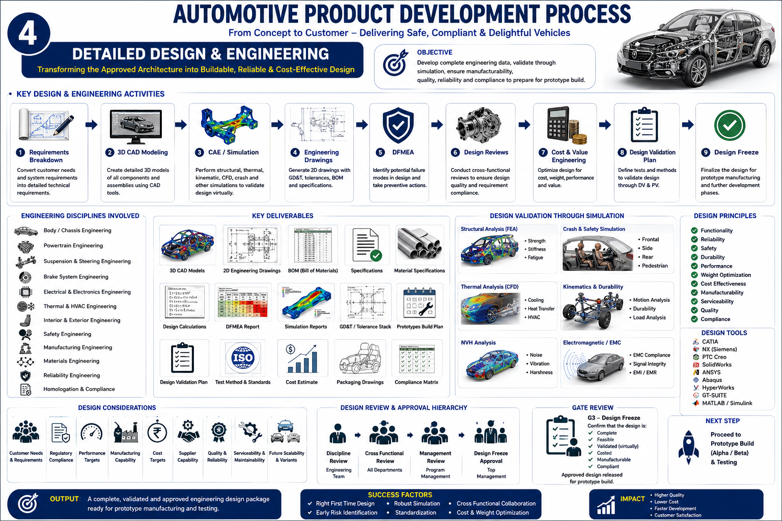
Detailed Design & Engineering in Automotive Product Development
Transforming Approved Vehicle Architecture into a Buildable, Reliable and Cost-Effective Design
Detailed Design & Engineering is one of the most critical phases in the Automotive Product Development Process. After the vehicle architecture and system concept are approved, the project moves into detailed engineering, where the concept is converted into complete engineering data suitable for prototype manufacturing, validation, tooling, supplier development, and future production.
This phase ensures that every component, system, interface, material, tolerance, assembly requirement, and performance target is clearly defined before the prototype build begins.
In simple words, this phase answers the question:
“How will the approved concept be engineered into a real, manufacturable, safe, reliable, and compliant vehicle?”
1. Objective of Detailed Design & Engineering
The main objective of the Detailed Design & Engineering phase is to develop complete engineering data and validate the design through analysis, simulation, design reviews, and manufacturability studies.
This phase focuses on ensuring that the vehicle design meets:
- Customer requirements
- Product performance targets
- Safety requirements
- Reliability and durability targets
- Manufacturing requirements
- Cost targets
- Quality expectations
- Regulatory and homologation requirements
- Serviceability and maintainability needs
The final output is a complete, validated, and approved engineering design package ready for prototype manufacturing and testing.
2. Key Design & Engineering Activities
2.1 Requirements Breakdown
The first step is to convert customer needs, product requirements, and system targets into detailed engineering requirements.
For example, a customer requirement such as “good ride comfort” must be converted into measurable technical targets such as:
This breakdown ensures that design engineers work with clear, measurable, and verifiable targets.
2.2 3D CAD Modelling
After requirements are finalized, engineers create detailed 3D CAD models of all components, assemblies, and systems.
This includes:
- Body panels
- Chassis/frame
- Engine parts
- Suspension components
- Brake system parts
- Electrical brackets
- Plastic trims
- Interior parts
- Exterior parts
- Mounting brackets
- Fasteners
- Packaging envelopes
CAD modelling helps engineers check component geometry, packaging, assembly feasibility, and system integration before physical parts are manufactured.
Common CAD tools include CATIA, Siemens NX, Creo, SolidWorks, and Autodesk Inventor.
2.3 CAE / Simulation
CAE simulation helps validate the design virtually before prototype manufacturing. This reduces development time, cost, and physical testing failures.
Typical CAE activities include:
- Structural analysis
- Crash simulation
- Thermal analysis
- Durability simulation
- Kinematics analysis
- NVH analysis
- CFD analysis
- Fatigue analysis
- Electromagnetic compatibility analysis
Simulation does not completely replace physical testing, but it helps identify design weaknesses early and improves the design before prototype build.
2.4 Engineering Drawings
After CAD models are created, engineering drawings are prepared for manufacturing, supplier development, inspection, and quality control.
Engineering drawings normally include:
- 2D drawing views
- Dimensions
- GD&T requirements
- Tolerance stack-up
- Material specifications
- Surface finish
- Heat treatment details
- Welding details
- Coating requirements
- Part number
- Revision history
- BOM reference
A good engineering drawing must clearly communicate design intent to manufacturing teams, suppliers, and quality inspectors.
2.5 DFMEA – Design Failure Mode and Effects Analysis
DFMEA is used to identify possible failure modes in the design and take preventive action before the product reaches customers.
Typical DFMEA questions include:
What can fail?
Why can it fail?
What will be the effect of failure?
How severe is the failure?
How likely is the failure to occur?
How can the failure be detected?
What preventive action is required?
Examples
DFMEA helps improve product reliability, durability, safety, and customer satisfaction.
2.6 Design Reviews
Design reviews are conducted at different levels to verify that the design is complete, feasible, and aligned with requirements.
Typical design reviews include:
- Discipline review
- Cross-functional review
- Supplier review
- Manufacturing review
- Quality review
- Serviceability review
- Homologation review
- Management review
The purpose of design review is to identify open issues before the design is frozen.
2.7 Cost & Value Engineering
A technically strong design must also be cost-effective. Cost and value engineering ensures the product delivers the required performance at the right cost.
Typical activities include:
- BOM cost review
- Material optimization
- Part commonization
- Manufacturing process optimization
- Localization study
- Supplier cost review
- Weight reduction
- Design simplification
- Standard part usage
Example:
Instead of designing a new bracket, an existing proven bracket may be reused with minor modification. This can reduce development cost, tooling cost, validation effort, and supplier complexity.
2.8 Design Validation Plan
The Design Validation Plan defines how the design will be verified and validated during DV and PV testing.
It includes:
- Test items
- Test methods
- Test standards
- Acceptance criteria
- Test duration
- Sample quantity
- Responsibility
- Timeline
- Reporting method
The Design Validation Plan ensures that every design requirement has a corresponding verification method.
2.9 Design Freeze
Design Freeze is the formal approval point where the engineering design is released for prototype manufacturing and further development.
At this stage, the design should be:
- Complete
- Feasible
- Reviewed
- Virtually validated
- Costed
- Manufacturable
- Compliant
- Ready for prototype build
Once the design is frozen, any design change must be controlled through a formal engineering change management process.
3. Engineering Disciplines Involved
Detailed Design & Engineering requires strong coordination between multiple engineering departments.
Body / Chassis Engineering
Responsible for body structure, frame, mounting points, crash load paths, stiffness, strength, and structural durability.
Powertrain Engineering
Responsible for engine, transmission, driveline, intake, exhaust, cooling, fuel system, hybrid system, or EV propulsion system.
Suspension & Steering Engineering
Responsible for ride comfort, handling, steering response, wheel movement, suspension geometry, and vehicle stability.
Brake System Engineering
Responsible for brake performance, ABS integration, hydraulic routing, brake hose layout, brake pedal feel, and regulatory compliance.
Electrical & Electronics Engineering
Responsible for wiring harness, ECU layout, sensors, actuators, power distribution, diagnostics, software interfaces, and communication networks.
Thermal & HVAC Engineering
Responsible for cooling system, heat transfer, HVAC performance, battery thermal management, engine cooling, and cabin comfort.
Interior & Exterior Engineering
Responsible for trims, panels, lighting layout, styling feasibility, fit & finish, ergonomics, and customer-facing parts.
Safety Engineering
Responsible for crashworthiness, occupant protection, pedestrian safety, functional safety, and safety-related systems.
Manufacturing Engineering
Responsible for process feasibility, tooling, assembly sequence, plant compatibility, automation, and production readiness.
Materials Engineering
Responsible for material selection, strength, durability, corrosion protection, weight reduction, recyclability, and cost.
Reliability Engineering
Responsible for durability targets, failure prevention, life cycle performance, and long-term field reliability.
Homologation & Compliance
Responsible for ensuring the design can meet applicable regulatory requirements such as emissions, safety, braking, lighting, noise, EMC, OBD, battery safety, and other market-specific regulations.
4. Key Deliverables of Detailed Design & Engineering
The image shows several important deliverables from this phase. These deliverables form the engineering foundation for prototype manufacturing, validation, homologation, and production preparation.
These documents must be controlled properly through document revision and engineering change management.
5. Design Validation Through Simulation
Simulation is a major part of modern automotive engineering. It helps engineers evaluate design performance before physical testing.
5.1 Structural Analysis
Structural analysis is used to check:
- Strength
- Stiffness
- Fatigue life
- Load carrying capability
- Mounting point durability
- Body and chassis integrity
This is useful for frames, brackets, suspension arms, engine mounts, chassis members, and body structures.
5.2 Crash & Safety Simulation
Crash simulation helps evaluate safety performance before physical crash testing.
Typical simulations include:
- Frontal impact
- Side impact
- Rear impact
- Pedestrian protection
- Battery protection in EVs
- Occupant protection
- Airbag deployment strategy
Crash simulation is important because physical crash testing is costly and time-consuming.
5.3 Thermal Analysis / CFD
Thermal analysis ensures that heat is properly managed in the vehicle.
It is used for:
- Engine cooling
- Radiator performance
- Battery cooling
- Motor and inverter cooling
- HVAC performance
- Brake cooling
- Under-hood temperature management
In EVs, thermal management is especially important for battery safety, performance, range, and life.
5.4 Kinematics & Durability
Kinematic and durability analysis is used for moving systems.
It helps evaluate:
- Suspension movement
- Steering geometry
- Wheel travel
- Linkage motion
- Load transfer
- Fatigue durability
- Road load response
This is important for suspension systems, steering systems, chassis systems, and vehicle handling.
5.5 NVH Analysis
NVH stands for Noise, Vibration, and Harshness.
NVH analysis helps reduce:
- Engine noise
- Road noise
- Wind noise
- Vibration
- Resonance
- Harshness
- Buzz, squeak, and rattle
Good NVH performance improves customer perception of quality and comfort.
5.6 Electromagnetic / EMC Analysis
EMC analysis ensures that electrical and electronic systems do not interfere with each other.
It evaluates:
- Electromagnetic compatibility
- Electromagnetic interference
- Signal integrity
- Electrical noise
- ECU communication reliability
- Sensor signal stability
This is especially important in modern vehicles with multiple ECUs, sensors, connectivity systems, EV power electronics, and ADAS systems.
6. Design Principles
A good automotive design must satisfy multiple principles at the same time.
Functionality
The design must perform its intended function under all defined operating conditions.
Reliability
The design must perform consistently over the expected vehicle life.
Safety
The design must protect the customer, service technician, and road users.
Durability
The design must withstand fatigue, vibration, corrosion, temperature, and real-world usage.
Performance
The design must meet acceleration, braking, handling, range, fuel economy, comfort, and system performance targets.
Weight Optimization
The design should meet strength and performance targets with minimum unnecessary weight.
Cost Effectiveness
The design must meet cost targets while maintaining quality and performance.
Manufacturability
The design must be easy and practical to manufacture at the required production volume.
Serviceability
The design must allow inspection, maintenance, diagnosis, repair, and replacement.
Quality
The design must support consistent manufacturing quality and customer satisfaction.
Compliance
The design must meet applicable regulatory, safety, environmental, and homologation requirements.
7. Design Tools Used in Detailed Engineering
Common tools used during this phase include:
Tool selection depends on OEM standards, supplier capability, project complexity, and engineering domain.
8. Design Considerations
During detailed engineering, engineers must balance several design considerations.
Customer Needs & Requirements
The design must satisfy the voice of customer and product positioning.
Regulatory Compliance
Compliance must be considered early to avoid costly redesigns later.
Performance Targets
Targets such as speed, acceleration, braking distance, range, fuel economy, ride comfort, and handling must be achieved.
Manufacturing Capability
The design must be compatible with available manufacturing processes and plant capability.
Cost Targets
Design decisions must remain within approved product cost and investment targets.
Supplier Capability
Supplier process capability, technology readiness, quality level, and delivery capacity must be considered.
Quality & Reliability
The design should prevent field failures, warranty claims, and customer dissatisfaction.
Serviceability & Maintainability
Parts requiring periodic inspection or replacement should be accessible.
Future Scalability & Variants
Design should support future model updates, regional variants, engine options, EV variants, and feature upgrades where possible.
9. Design Review & Approval Hierarchy
Detailed Design & Engineering normally follows a structured review process.
Discipline Review
Conducted within the engineering team responsible for the component or system.
Purpose
- Check technical correctness
- Review calculations
- Review CAD models
- Review drawings
- Confirm internal engineering standards
Cross-Functional Review
Conducted with multiple departments.
Participants may include:
- Design Engineering
- Manufacturing
- Quality
- Procurement
- Supplier Quality
- Service
- Homologation
- Cost Planning
Purpose
- Identify cross-functional concerns
- Check manufacturability
- Check serviceability
- Check compliance
- Review cost and quality risks
Management Review
Conducted by program management and senior leadership.
Purpose
- Confirm project readiness
- Review cost, timing, and risk
- Approve major decisions
- Resolve escalated issues
Design Freeze Approval
Final approval by top management or designated project authority.
Purpose
- Release design for prototype manufacturing
- Confirm design maturity
- Control further changes
10. Gate Review – G3 Design Freeze
The Detailed Design & Engineering phase ends with Gate G3 – Design Freeze.
At G3, the project team confirms that the design is:
- Complete
- Feasible
- Virtually validated
- Costed
- Manufacturable
- Compliant
- Ready for prototype build
Approval at this gate allows the project to proceed to the next phase:
Prototype Build – Alpha / Beta & Testing
11. Success Factors
Successful Detailed Design & Engineering depends on the following:
- Right-first-time design
- Early risk identification
- Robust simulation
- Standardization
- Cross-functional collaboration
- Cost and weight optimization
- Strong design review process
- Clear engineering ownership
- Effective supplier involvement
- Proper engineering change control
When these success factors are followed, the project can reduce late changes, improve quality, control cost, and accelerate development.
12. Impact of Effective Detailed Design & Engineering
A strong Detailed Design & Engineering phase creates major benefits for the complete product development program.
13. Practical Example: Motorcycle Detailed Design
For a motorcycle project, detailed engineering may include:
- Frame CAD design
- Engine mounting bracket design
- Fuel tank packaging
- Exhaust routing
- Radiator location
- ABS modulator packaging
- Brake hose routing
- Wiring harness routing
- Headlamp and indicator mounting
- Suspension geometry
- Side stand design
- Seat and rider triangle
- Service access for air filter, spark plug, battery, and ECU
- Compliance with lighting, braking, noise, emission, and safety requirements
Even a small bracket design change can affect weight, durability, cost, serviceability, and homologation documentation.
14. Practical Example: EV Detailed Design
For an EV project, detailed engineering may include:
- Battery pack mounting
- Battery enclosure design
- High-voltage cable routing
- Motor mounting
- Inverter cooling
- Charger placement
- Thermal management
- BMS integration
- HV safety isolation
- Crash protection for battery
- EMC performance
- Software and diagnostics
- Charging inlet location
- Service safety procedure
EV design requires close coordination between mechanical, electrical, thermal, software, safety, and compliance teams.
15. Common Risks in Detailed Design & Engineering
Typical risks include:
- Incomplete requirements
- Late regulatory understanding
- Poor packaging
- Tolerance stack-up issues
- Supplier capability mismatch
- Overweight design
- Cost target failure
- Inadequate DFMEA
- Weak simulation assumptions
- Poor serviceability
- Manufacturing infeasibility
- Drawing errors
- Interface mismatch
- Late engineering changes
- Insufficient design review
These risks must be tracked through an issue list, DFMEA, design review records, and project risk register.
16. Best Practices
For effective Detailed Design & Engineering, OEMs and suppliers should follow these practices:
Start with clear and approved requirements.
Maintain strong requirement traceability.
Use proven design standards wherever possible.
Conduct packaging reviews regularly.
Complete DFMEA before design freeze.
Use CAE simulation before physical prototype release.
Involve manufacturing, quality, service, supplier, and homologation teams early.
Review cost and weight at every design stage.
Control drawing revisions strictly.
Use GD&T properly to avoid assembly and quality issues.
Maintain a live open-issue list.
Avoid late design changes after design freeze.
Conduct formal G3 Design Freeze review before prototype build.
Conclusion
Detailed Design & Engineering converts the approved vehicle architecture into a complete engineering design package. This phase defines the actual parts, systems, materials, tolerances, interfaces, manufacturing requirements, validation plans, and compliance strategy.
A strong design and engineering process improves product quality, reduces development risk, supports manufacturability, controls cost, improves serviceability, and ensures readiness for prototype manufacturing.
The final output of this phase is:
A complete, validated, and approved engineering design package ready for prototype manufacturing and testing.
Key Takeaways
Detailed Design & Engineering converts vehicle architecture into buildable engineering data.
CAD, CAE, DFMEA, design reviews, drawings, BOM, and validation plans are core outputs.
Cross-functional reviews are essential to ensure manufacturability, cost, quality, serviceability, and compliance.
Simulation helps reduce physical testing failures and development cost.
G3 Design Freeze is the key milestone before prototype build.
Strong engineering discipline at this stage directly improves vehicle quality, safety, reliability, and customer satisfaction.
Reference tables from the source chapter
| Customer Requirement | Engineering Requirement |
|---|---|
| Comfortable ride | Suspension travel, spring rate, damping force |
| Good braking | Braking distance, brake force distribution |
| Good fuel economy | Vehicle weight, engine efficiency, aerodynamics |
| Premium feel | Material finish, fit & finish, NVH target |
| Easy maintenance | Service access, tool accessibility, service interval |
Reference table 2
| Component | Possible Failure Mode | Possible Effect |
|---|---|---|
| Brake hose | Leakage | Reduced braking performance |
| Engine bracket | Crack | Vibration or engine movement |
| Wiring harness | Heat damage | Electrical failure |
| Suspension arm | Fatigue failure | Handling issue |
| Fuel pipe | Leakage | Safety risk |
Reference table 3
| Deliverable | Purpose |
|---|---|
| 3D CAD Models | Complete digital representation of parts and assemblies |
| 2D Engineering Drawings | Manufacturing and inspection reference |
| BOM | List of all parts, materials, and assemblies |
| Specifications | Technical requirements for components and systems |
| Material Specifications | Material grade, treatment, coating, and performance needs |
| Design Calculations | Engineering proof for strength, load, performance, and function |
| DFMEA Report | Risk analysis and preventive action plan |
| Simulation Reports | CAE validation evidence |
| GD&T / Tolerance Stack | Dimensional control and assembly fitment |
| Prototype Build Plan | Plan for prototype parts and vehicle assembly |
| Design Validation Plan | Test plan for design verification |
| Test Methods & Standards | Reference standards and acceptance criteria |
| Cost Estimate | Estimated development, part, and manufacturing cost |
| Packaging Drawings | System layout and component arrangement |
| Compliance Matrix | Regulatory requirement tracking |
Reference table 4
| Tool | Purpose |
|---|---|
| CATIA | CAD design and packaging |
| Siemens NX | CAD and engineering design |
| PTC Creo | CAD modelling |
| SolidWorks | CAD modelling |
| ANSYS | Structural, thermal, CFD, and multiphysics analysis |
| Abaqus | Advanced structural and nonlinear simulation |
| HyperWorks | CAE pre-processing, solving, and optimization |
| GT-SUITE | Powertrain, thermal, and system simulation |
| MATLAB / Simulink | Control logic, model-based design, and system simulation |
Reference table 5
| Area | Impact |
|---|---|
| Quality | Fewer design-related failures |
| Cost | Reduced rework and optimized BOM cost |
| Development Time | Faster prototype and validation phase |
| Customer Satisfaction | Better performance, reliability, and serviceability |
| Manufacturing | Fewer production issues |
| Homologation | Reduced compliance risk |
| Supplier Development | Clear technical requirements |
| Warranty | Lower field failure risk |
Frequently asked questions
What is included in a detailed engineering release?
A release normally includes controlled 3D models, drawings, specifications, calculations, BOM data, simulation evidence, DFMEA actions, and validation requirements.
How does CAE support detailed design?
Structural, thermal, crash, CFD, durability, NVH, and electromagnetic simulations expose weaknesses early and guide design trade-offs before physical testing.
What is design freeze?
Design freeze is the controlled approval of a sufficiently mature design for prototype or production-intent activity, with remaining changes handled through formal change control.
Related articles
Phase review toolkit
Why this phase matters
Detailed engineering converts system intent into reproducible definitions that suppliers, prototypes, tests and plants can execute.
Inputs, outputs and gate review
- Inputs: Released architecture, system requirements, interfaces, load cases and design standards.
- Outputs: Production-intent drawings, models, specifications, software baselines, DFMEA actions and verification evidence.
- Gate-review summary: Confirm design maturity, interface compatibility, risk closure and the evidence needed for prototype and validation release.
Chapter Checklist
- Inputs are controlled and traceable
- Outputs have an accountable owner and approval status
- Open risks include containment, due date and decision authority
- Configuration and assumptions match downstream evidence
- Compliance and change impacts are recorded