Functional Safety (FuSa) in Automotive
Engineering Deep Dive · Vehicle Safety
ISO 26262, HARA, ASIL and the Safety Lifecycle
Modern vehicles depend on interconnected electrical and electronic systems for engine control, braking, steering, stability, battery management, lighting, rider or driver assistance, instrumentation and connectivity. A malfunction in one sensor, electronic control unit, communication link, power supply, actuator or software function can therefore influence vehicle behaviour within milliseconds.
Automotive functional safety—commonly abbreviated as FuSa—is the disciplined engineering approach used to prevent these malfunctions from creating unreasonable risk to the driver, rider, passengers, service personnel or other road users. It does not promise that electronic components will never fail. Instead, it requires hazards to be identified systematically, safety requirements to be derived from the risk, faults to be detected or controlled, and objective evidence to be produced throughout the product lifecycle.
Functional safety infographic
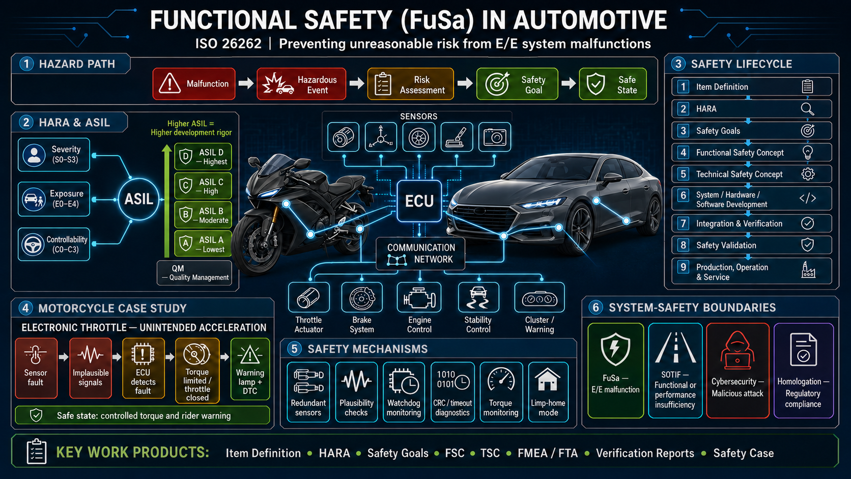
1. What does functional safety mean?
Functional safety is the part of overall vehicle safety that depends on a safety-related electrical or electronic system operating correctly—or responding safely when it does not operate correctly.
The main international framework is the ISO 26262 series, Road vehicles—Functional safety. ISO explains that the standard addresses hazards caused by the malfunctioning behaviour of safety-related electrical and electronic systems, including interactions between those systems. It covers both technical requirements and process requirements across development, production, operation, service and decommissioning. The currently published series is the 2018 edition; revision work on a future edition is underway as of July 2026. See the official ISO 26262-1:2018 overview.
A useful way to understand FuSa is:
A fault may occur, but the vehicle must detect, tolerate or control it early enough to prevent an unreasonable safety risk.
This leads to the hazard-control path shown in the infographic:
Malfunction → Hazardous event → Risk assessment → Safety goal → Safe state
Each term has a specific engineering purpose:
- A malfunction is the loss, incorrect execution or unintended execution of a function.
- A hazard is a potential source of harm.
- A hazardous event combines a hazard with a particular operational situation—for example, unintended drive torque while the motorcycle is cornering on a wet road.
- A safety goal is a high-level vehicle safety requirement derived from one or more hazardous events.
- A safe state is an operating condition in which unreasonable risk is avoided or sufficiently controlled.
- Residual risk is the risk that remains after safety measures have been implemented.
Functional safety must be considered at vehicle level. A sensor, microcontroller or ECU is not “safe” in isolation merely because it has diagnostics. Its safety contribution depends on the intended function, interfaces, operating environment, assumed external measures, system architecture and vehicle-level hazardous events.
2. Why FuSa has become essential
Mechanical systems increasingly depend on electronics. Examples include:
- Electronic throttle control
- Anti-lock braking systems
- Cornering ABS and stability control
- Traction and wheelie control
- Electric power steering and steer-by-wire functions
- Brake-by-wire and regenerative braking
- Automatic emergency braking
- Adaptive cruise control
- Airbag and restraint control
- High-voltage battery management
- Electric traction inverters and motor control
- Electronic suspension
- Body controllers, gateways and vehicle communication networks
- Instrument clusters, tell-tales and safety warnings
- Advanced rider- and driver-assistance functions
The safety challenge is not limited to a complete loss of function. An electronic system can fail by producing an output that is too high, too low, delayed, intermittent, active at the wrong time or inconsistent with the driver’s or rider’s request. A plausible-looking but incorrect signal can be more dangerous than a complete signal loss because the receiving ECU may continue to act on it.
FuSa provides a repeatable method to manage this complexity. It improves:
- Early identification of vehicle-level hazards
- Traceability from hazards to design and test evidence
- Coordination between OEMs and suppliers
- Treatment of systematic and random hardware failures
- Software development discipline
- Independence and effectiveness of safety mechanisms
- Production and service controls
- Management of design changes and software updates
- Confidence during safety reviews, customer assessments and product release
FuSa should therefore be treated as a core product-development activity, not as a final test conducted shortly before start of production.
3. Scope—and important limits—of ISO 26262
ISO 26262 applies to safety-related electrical and electronic systems installed in series-production road vehicles within the scope defined by the standard. The 2018 edition expanded the original passenger-car focus and includes an adaptation for motorcycles in Part 12. Mopeds are excluded from the stated scope. The motorcycle adaptation addresses safety culture, confirmation measures, HARA, vehicle integration, testing and safety validation. See ISO 26262-12:2018.
ISO 26262 primarily addresses hazards caused by malfunctioning E/E behaviour. It does not, by itself, provide complete coverage for every vehicle hazard. Other disciplines remain necessary for:
- Mechanical structural integrity
- Fire, thermal runaway and chemical hazards
- Electric shock and high-voltage safety
- Flammability, toxicity and material hazards
- Environmental durability and electromagnetic compatibility
- Occupational and manufacturing safety
- Cybersecurity
- Safety limitations of a correctly functioning automated system
- Compliance with market-specific vehicle regulations
These disciplines can interact. For example, a battery-cell internal defect is primarily a cell and battery safety issue; however, failure of the battery-management system to detect overtemperature or command isolation may also create a functional-safety concern.
4. How the ISO 26262 series is organised
ISO 26262 is a multi-part lifecycle standard rather than a single product test.
| Part | Primary subject |
|---|---|
| ISO 26262-1 | Vocabulary |
| ISO 26262-2 | Management of functional safety |
| ISO 26262-3 | Concept phase: item definition, HARA and functional safety concept |
| ISO 26262-4 | Product development at the system level |
| ISO 26262-5 | Product development at the hardware level |
| ISO 26262-6 | Product development at the software level |
| ISO 26262-7 | Production, operation, service and decommissioning |
| ISO 26262-8 | Supporting processes |
| ISO 26262-9 | ASIL-oriented and safety-oriented analyses |
| ISO 26262-10 | Guidelines on ISO 26262 |
| ISO 26262-11 | Guidance for applying ISO 26262 to semiconductors |
| ISO 26262-12 | Adaptation for motorcycles |
The concept phase is defined in ISO 26262-3:2018. System development is addressed in Part 4, hardware in Part 5, software in Part 6, lifecycle operations in Part 7, supporting processes in Part 8, safety-oriented analyses in Part 9, semiconductor guidance in Part 11, and motorcycle adaptation in Part 12.
5. Functional safety management and safety culture
FuSa begins with organisational behaviour. A sophisticated safety mechanism cannot compensate for unclear ownership, uncontrolled changes, incomplete requirements or a culture that prioritises schedule over unresolved safety concerns.
A functional-safety management system should establish:
- A documented safety policy and safety culture
- Competent and adequately independent personnel
- A project functional-safety manager
- A functional-safety plan
- Responsibilities, authorities and escalation paths
- Tailoring of applicable lifecycle activities
- Supplier and distributed-development interfaces
- Confirmation reviews, functional-safety audits and assessments
- Control of safety anomalies and unresolved issues
- Criteria for release for production
The safety plan defines what must be done, by whom, when, with which competence, using which methods and tools, and with what degree of independence. It should be integrated with the overall product-development plan rather than maintained as a parallel paperwork exercise.
In distributed development, the OEM and supplier must agree on safety responsibilities, assumptions, interfaces, work products, review rights and evidence delivery. This is commonly managed through a Development Interface Agreement (DIA) or an equivalent controlled agreement. Unclear allocation between OEM, Tier 1, Tier 2 and semiconductor suppliers is a common source of safety gaps.
6. Item definition: the foundation of HARA
The item definition describes the function or set of functions to which the safety lifecycle will be applied. It establishes the boundaries of the analysis.
A good item definition normally includes:
- Intended functions and operating modes
- System boundary and external interfaces
- Sensors, controllers, communication paths and actuators
- Interaction with the driver or rider
- Interaction with other vehicle functions
- Environmental and operating conditions
- Available external safety mechanisms
- Assumptions about other systems
- Known limitations and dependencies
- Variants, configurations and market differences
For an electronic throttle-control item, the boundary may include the accelerator-grip or pedal sensors, engine ECU, throttle-body sensors, actuator motor, power supply, communication interfaces, torque-control software, warning strategy and relevant interfaces with traction control, braking and transmission systems.
A generic or copied item definition leads to a generic HARA. The official motorcycle HARA guidance emphasises that risk analysis must be based on the specific item and its actual vehicle context rather than generic example values. See ISO/TR 5340:2023.
7. HARA: Hazard Analysis and Risk Assessment
HARA is used during the concept phase to identify and classify hazardous events resulting from malfunctioning behaviour.
7.1 Identify functions and malfunctions
For each function, the team considers credible malfunctioning behaviours, such as:
- Complete loss of function
- Unintended activation
- Function not available when demanded
- Excessive, insufficient or reversed output
- Incorrect timing or delayed response
- Intermittent or unstable output
- Incorrect information or warning
- Conflicting commands between systems
7.2 Define operational situations
Risk depends on the situation in which the malfunction occurs. Examples include:
- Vehicle stationary or moving
- Low-speed manoeuvring
- Urban traffic
- Highway operation
- Overtaking
- Corner entry or mid-corner
- Wet, icy or loose surfaces
- Uphill or downhill operation
- Rider standing on the foot pegs during off-road use
- Vehicle carrying a passenger or luggage
- Charging, servicing or workshop operation
7.3 Form hazardous events
A hazardous event combines the malfunction and operational situation. “Throttle sensor failure” is not yet a complete hazardous event. “Unintended high positive engine torque during a high-speed corner” is much closer to one because it describes the safety-relevant vehicle behaviour and context.
7.4 Classify Severity, Exposure and Controllability
The infographic correctly shows the three core HARA parameters:
| Parameter | Typical scale | Question answered |
|---|---|---|
| Severity | S0–S3 | How serious could the potential harm be? |
| Exposure | E0–E4 | How frequently is the relevant operating situation expected? |
| Controllability | C0–C3 | How likely is the driver, rider or another road user to control or avoid the harm? |
The classification must be supported by a reasoned argument and relevant data. Controllability is not the same as “an expert test rider can recover the vehicle.” It must consider the intended user population, realistic reaction time, vehicle dynamics, traffic, road surface, visibility and the warning available before the hazardous behaviour develops.
7.5 Determine the integrity level
For general automotive application, the combination of Severity, Exposure and Controllability leads to QM or an Automotive Safety Integrity Level (ASIL) from A to D:
| Classification | General interpretation | Development consequence |
|---|---|---|
| QM | Managed through established quality-management processes | No additional ISO 26262 ASIL requirements are assigned by the HARA |
| ASIL A | Lower safety integrity | Additional safety engineering and verification discipline |
| ASIL B | Moderate safety integrity | Stronger methods, evidence and independence |
| ASIL C | High safety integrity | High diagnostic and development rigour |
| ASIL D | Highest safety integrity | Most demanding methods, evidence and confirmation measures |
Higher ASIL means greater required confidence in preventing or controlling the safety-goal violation. It does not simply mean “more testing,” and it is not a probability that an accident will happen.
Important motorcycle terminology
The infographic uses ASIL as the widely recognised automotive integrity scale. For motorcycle-specific application, ISO 26262 includes the term MSIL—Motorcycle Safety Integrity Level. Four motorcycle levels are used—MSIL A to MSIL D, with MSIL D the most stringent—and QM remains outside the MSIL scale. The same letter does not mean that an MSIL is automatically identical to the corresponding ASIL; the motorcycle adaptation defines how the required risk reduction is related to the ISO 26262 lifecycle. Project documentation should therefore use the terminology and method applicable to ISO 26262-12 rather than copying passenger-car ASIL assumptions. The standard’s vocabulary identifies MSIL as the output of the motorcycle HARA, while ISO 26262-12 provides the adaptation and ISO/TR 5340:2023 provides motorcycle HARA use cases.
The key engineering principle remains the same: the integrity level follows from the vehicle- and item-specific HARA. It must not be selected because an ECU, sensor or feature “sounds safety critical.”
8. Safety goals, safe states and fault-tolerant timing
Safety goals are top-level safety requirements derived from hazardous events. They should describe the safety intent, not prematurely prescribe a component solution.
Examples for an electronic throttle system might include:
- Prevent unintended positive drive torque beyond the controllable limit.
- Prevent loss of controllable torque reduction when demanded by the rider.
- Detect disagreement between demanded and delivered torque and transition to a controlled condition.
- Provide an appropriate warning when continued normal operation cannot be assured.
Safe state
A safe state is system- and situation-dependent. It is not always “switch everything off.” Abrupt engine shutdown while overtaking, loss of brake assistance during braking, or high-voltage isolation while high traction power is required can create a new hazard.
Possible safety responses include:
- Immediate controlled shutdown
- Torque limitation
- Maintaining a limited function
- Graceful degradation
- Driver or rider takeover request
- Emergency operation for a limited time
- Controlled transition followed by shutdown
The design must also consider the Fault-Tolerant Time Interval (FTTI)—the time available between fault occurrence and the point at which a hazardous event must be prevented. Detection, decision-making, actuation and transition to the safe or degraded state must all fit within this available time.
9. Functional Safety Concept and Technical Safety Concept
9.1 Functional Safety Concept (FSC)
The Functional Safety Concept translates safety goals into functional safety requirements at the vehicle or item level.
It describes what safety behaviour is required, including:
- Fault detection
- Fault tolerance
- Degraded operation
- Driver or rider warning
- Safe-state transition
- Required independence
- Timing constraints
- External measures and assumptions
The FSC should remain sufficiently solution-neutral. For example, it may require detection of incompatible throttle-demand signals within a defined time without yet specifying the exact microcontroller peripheral or circuit used.
9.2 Technical Safety Concept (TSC)
The Technical Safety Concept converts functional safety requirements into implementable technical safety requirements and allocates them to system elements.
It defines:
- System architecture
- Sensor and actuator diagnostics
- ECU monitoring
- Hardware and software partitioning
- Communication protection
- Power-supply monitoring
- Timing supervision
- Warning and diagnostic behaviour
- Redundancy and independence
- Hardware-software interface requirements
- Integration and verification criteria
The TSC provides the bridge between vehicle-level safety intent and detailed hardware and software design.
10. System, hardware and software development
10.1 System-level development
System development defines the technical safety requirements, architecture, interfaces, integration strategy and vehicle-level validation approach. Requirements must be allocated to the correct elements and traced in both directions:
- Hazardous event → safety goal
- Safety goal → functional safety requirement
- Functional requirement → technical requirement
- Technical requirement → hardware/software implementation
- Implementation → verification test
- Safety goal → vehicle-level safety validation
Bidirectional traceability helps demonstrate that every safety requirement is implemented and tested, and that every safety-related design element exists for a justified requirement.
10.2 Hardware-level development
Hardware safety work addresses both systematic design weaknesses and random physical failures. Typical activities include:
- Hardware safety-requirement specification
- Hardware architectural design
- Failure-mode analysis
- Diagnostic-coverage evaluation
- Analysis of single-point, residual and latent faults
- Evaluation of dependent failures
- Probabilistic evaluation of random hardware failures
- Hardware integration and verification
Common hardware metrics include:
- SPFM—Single-Point Fault Metric: indicates how effectively the architecture avoids safety-goal violations from single-point and residual faults.
- LFM—Latent Fault Metric: indicates how effectively latent multiple-point faults are detected or controlled.
- PMHF—Probabilistic Metric for random Hardware Failures: evaluates the estimated rate of safety-goal violation caused by random hardware failures.
Applicable numerical targets depend on the assigned integrity level and the precise standard requirements. Project teams should use the licensed standard and approved organisational methods rather than relying on abbreviated online tables.
10.3 Software-level development
Software safety is managed through disciplined requirements, architecture, implementation and verification. Key topics include:
- Software safety requirements
- Software architecture and unit design
- Defensive programming and coding guidelines
- Data and control-flow monitoring
- Range, plausibility and timing checks
- Freedom from interference between mixed-criticality software
- Software unit verification
- Software integration and embedded-software testing
- Configuration and change management
- Qualification or confidence in software tools where required
More code and more diagnostics do not automatically create a safer system. The software architecture must make safety assumptions explicit and control shared resources such as memory, CPU time, communication buffers and peripheral access.
11. Safety analyses used in FuSa
No single analysis method can identify every fault path. Functional-safety programmes normally combine inductive and deductive techniques.
| Method | Starting point | Main purpose |
|---|---|---|
| FMEA | Component or function failure mode | Determine local and higher-level effects and controls |
| FMEDA | Detailed hardware failure modes and diagnostic measures | Quantify failure categories and diagnostic coverage |
| FTA | Top-level undesired event | Identify combinations of causes that could produce the event |
| DFA | Shared resources and dependencies | Identify common-cause, cascading and dependent failures |
| Interface analysis | Signals, timing, assumptions and responsibilities | Prevent gaps at ECU, network and supplier boundaries |
Safety analyses should influence design decisions. An FMEA completed after design freeze only to close a checklist has limited value.
Failure categories that must be considered
- Systematic failures: introduced by specification, architecture, design, coding, manufacturing process or maintenance errors. These are addressed mainly through disciplined lifecycle processes, methods, verification and confirmation measures.
- Random hardware failures: physical failures that can occur unpredictably over time. These are addressed through robust architecture, diagnostics, failure-rate evaluation and safety mechanisms.
- Dependent failures: multiple elements failing because of a shared cause, shared resource, environmental condition or cascading effect.
- Latent failures: faults that remain undetected until another fault occurs and together violate a safety goal.
Redundancy is useful only when sufficient independence exists. Two identical sensors using the same power supply, connector, ground path, software and environmental location may fail together and therefore may not provide the expected risk reduction.
12. Typical automotive safety mechanisms
The infographic shows several common mechanisms. Their purpose is explained below.
Redundant sensors
Two or more sensing channels can permit comparison and fault detection. Good designs consider independence, separate signal paths, reference voltages, connector pins and failure modes. Redundancy without diversity or independence can leave common-cause faults unresolved.
Plausibility checks
A signal may be electrically valid but physically impossible. Plausibility monitoring compares:
- Two channels of the same sensor
- Requested and actual actuator position
- Vehicle speed and wheel speeds
- Engine speed and selected gear
- Steering input and measured yaw response
- Battery current, voltage and state-of-charge behaviour
Watchdog monitoring
Hardware or software watchdogs supervise execution timing and ECU health. A watchdog must be sufficiently independent of the function it monitors; otherwise, the same failure may disable both the control function and the monitor.
Communication protection
Safety-related communication may require:
- Message counters
- Cyclic redundancy checks
- Timeouts
- Source and destination identifiers
- Sequence monitoring
- Data freshness checks
- Defined fallback behaviour after communication loss
A standard network-level CRC alone may not cover every end-to-end failure between the transmitting application and receiving application.
Torque and actuator monitoring
An independent monitoring path can compare requested torque, permitted torque and delivered torque. Actuator-position feedback can detect disagreement between the command and physical response.
Diagnostic coverage and warning
Diagnostics must detect relevant faults within the required time and trigger the correct reaction. A DTC and warning lamp are important for service and user information, but a warning alone is normally insufficient if the hazardous event can develop before the user can respond.
Limp-home or degraded mode
Degraded operation can maintain limited mobility while controlling risk. Limits must be based on the HARA and verified at vehicle level. A degraded mode is safe only if its performance, duration, warning and exit conditions are controlled.
13. Detailed motorcycle case study: unintended electronic-throttle acceleration
The infographic uses electronic throttle control to demonstrate the full FuSa chain.
13.1 Potential initiating faults
- Accelerator-grip sensor stuck high
- Sensor-channel disagreement
- Throttle-position sensor drift
- Open circuit or short to battery/ground
- Corrupted network torque request
- ECU memory or calculation error
- Software timing failure
- Actuator-driver fault
- Throttle plate or actuator jam
- Power-supply overvoltage, undervoltage or transient reset
13.2 Potential hazardous behaviour
The fault may result in unintended positive torque, failure to reduce torque, unstable torque oscillation or delayed throttle closure. Consequences depend on the situation:
- At standstill: unexpected launch
- In congested traffic: collision with another vehicle or pedestrian
- During overtaking: inability to regulate closing speed
- Mid-corner: loss of tyre-force balance, widening of the line or loss of stability
- On a wet or loose surface: wheel spin and loss of control
- During low-speed manoeuvring: fall or collision
Motorcycles require particular attention because stability depends strongly on speed, steering, tyre forces, lean angle, rider input and road surface. The rider also has less physical protection than a passenger-car occupant, and the controllability of a sudden torque disturbance can change significantly with the riding situation.
13.3 Example safety strategy
A possible safety strategy may include:
- Two accelerator-grip sensor channels with opposite or otherwise correlated characteristics.
- Independent plausibility checking of both grip channels.
- Dual throttle-position feedback.
- Comparison of requested, commanded and measured throttle or torque.
- Monitoring of MCU execution, memory, clocks, supply voltage and output drivers.
- Timeout and integrity checks for network torque requests.
- Mechanical return spring or other actuator fail-safe feature.
- Torque limitation when disagreement is detected.
- Controlled throttle closure where the operating situation permits it.
- Warning indication and storage of a diagnostic trouble code.
- Restricted restart or defined recovery conditions for critical faults.
The exact reaction must be determined by the safety concept. Immediate throttle closure may not be the safest response in every situation; the transition must remain stable and controllable.
13.4 Verification and validation examples
Fault-injection and vehicle-level tests may include:
- Sensor stuck-at and out-of-range faults
- Slow drift and rationality faults
- Short circuit and open circuit
- Disagreement between sensor channels
- Corrupted, delayed, repeated or missing network messages
- MCU reset, timing overrun and watchdog activation
- Memory corruption
- Actuator-driver faults
- Throttle-plate obstruction
- Supply-voltage interruption and recovery
- Warning and DTC verification
- Recovery, key-cycle and restart behaviour
- Response-time measurement against the safety timing requirement
- Vehicle controllability in representative operating scenarios
Component tests demonstrate local behaviour; final safety validation must show that the integrated vehicle achieves its safety goals in the intended operating context.
14. Passenger-car functional safety: systems, hazards and case studies
Passenger cars use the same fundamental ISO 26262 principles—item definition, HARA, safety goals, safety concepts, implementation and validation—but their vehicle architecture and risk context differ from motorcycles.
A passenger car normally has four-wheel stability, an enclosed occupant compartment, restraints and greater crash protection. At the same time, it may carry several occupants, travel at high speed, use powerful electronically controlled actuators and integrate many functions through domain or central vehicle computers. A single shared sensor, network, power supply or software platform may support propulsion, braking, steering and driver-assistance functions. This creates complex dependencies that must be analysed at vehicle level.
14.1 Safety-related E/E systems in passenger cars
The following car systems commonly require functional-safety consideration when their malfunction could create a vehicle-level hazard:
| Vehicle area | Example functions | Representative malfunctioning behaviour |
|---|---|---|
| Propulsion | Electronic throttle, engine torque control, transmission control | Unintended acceleration, excessive torque, inability to reduce torque, unexpected gear engagement |
| Braking | ABS, ESC, brake-by-wire, electric parking brake, regenerative braking | Loss of braking, unintended braking, asymmetric wheel braking, incorrect brake blending |
| Steering | Electric power steering, rear-wheel steering, steer-by-wire | Unintended steering torque, loss of assistance, incorrect steering angle, oscillation |
| Vehicle dynamics | Traction control, yaw control, active suspension | Destabilising intervention, unavailable intervention, incorrect wheel-torque control |
| Occupant protection | Airbag and pretensioner control, occupant detection | Unintended deployment, failure to deploy when required, incorrect suppression |
| Visibility and awareness | Exterior lighting, wipers, demisting, cluster warnings | Loss of required visibility, incorrect safety warning or tell-tale |
| ADAS | AEB, lane support, adaptive cruise control, parking assistance | Unintended intervention, missed intervention due to a fault, incorrect acceleration or steering command |
| Electric and hybrid powertrain | BMS, inverter, traction motor, HV interlock, charging control | Unintended propulsion, loss of propulsion, excessive regenerative braking, failure to isolate high voltage |
| Body and access | Powered doors, windows, tailgate and seat control | Trapping, unexpected movement or inability to provide required escape/access |
Not every electronic function automatically receives an ASIL. The classification depends on the specific malfunction, operational situation and HARA result. A comfort-seat function may normally be quality-managed, but unintended seat movement that seriously affects driver control could create a safety-relevant event.
14.2 Passenger-car HARA considerations
Car HARA should represent real operating situations and foreseeable users rather than only proving-ground conditions. Important factors include:
- Vehicle speed and road type
- Traffic density and surrounding road users
- Straight driving, lane changing and cornering
- Road friction, gradient and surface irregularities
- Parking and low-speed manoeuvring
- Towing or roof-load configuration where applicable
- Driver hands-on or hands-off condition
- Driver reaction time and physical steering/brake effort
- Vehicle loading and number of occupants
- Automated-system operating mode
- Availability of mechanical or hydraulic fallback
- Warning quality and time available for takeover
- Interaction with another failing or degraded function
The same technical fault can produce different hazardous events. Loss of electric steering assistance while parking may mainly increase driver effort; the same failure during an emergency avoidance manoeuvre can reduce controllability. Unintended steering torque at high speed may be more critical than loss of assistance, depending on magnitude, rate, duration and the driver’s ability to counteract it.
14.3 Detailed car case study: electric power steering
Electric Power Steering (EPS) assists the driver by using sensor inputs, an ECU, power electronics and an electric motor to generate steering-assistance torque. Advanced systems may also receive torque or angle requests from lane-support, parking and stability functions.
Item definition
An EPS item definition may include:
- Steering-wheel or torsion-bar torque sensors
- Steering-angle and motor-position sensing
- EPS ECU and application software
- Power stage, motor and current sensing
- Vehicle-speed and dynamics signals
- Power supply, ground and ignition interfaces
- Communication with ADAS and stability-control ECUs
- Driver warning and diagnostic interfaces
- Mechanical steering path or redundant steer-by-wire channels
- Thermal limits and degraded operating modes
The item boundary must clarify whether the steering column, rack, mechanical linkage, rear-steering actuator, ADAS controller and power supply are inside the item or external assumptions.
Potential initiating faults
- Torque-sensor offset, drift, stuck value or channel disagreement
- Incorrect steering-angle or motor-position signal
- Motor phase, inverter or current-sensor fault
- MCU calculation, memory, timing or clock failure
- Corrupted or delayed steering request from another ECU
- Vehicle-speed signal error causing excessive assistance
- Power-supply interruption, undervoltage or overvoltage
- Thermal overload
- Incorrect calibration or software variant
- Loss of communication with ADAS or stability control
- Common-cause failure affecting redundant channels
Potential hazardous behaviour
- Unintended steering torque
- Steering torque in the wrong direction
- Sudden loss or excessive reduction of steering assistance
- Excessive assistance causing over-response
- Steering oscillation
- Incorrect steering angle in a steer-by-wire or rear-steering system
- Failure to terminate an automated steering intervention
Representative hazardous events may include unintended steering during a high-speed lane change, sudden loss of assistance during collision avoidance, or incorrect automated-steering torque while driving beside another vehicle. The actual Severity, Exposure and Controllability classifications must be justified for the specific car and use case.
Example safety goals
Possible high-level safety goals include:
- Prevent unintended steering torque beyond the vehicle-level controllability limit.
- Prevent unintended steering angle in systems that electronically command road-wheel angle.
- Detect incompatible torque, angle or motor-position information within the defined safety time.
- Maintain or transition to a controllable steering condition following a detected fault.
- Prevent a faulty external steering request from creating an unsafe road-wheel response.
- Warn the driver when the required steering support or automated function is unavailable.
These are illustrative safety intents, not ready-made requirements for every EPS project.
Typical EPS safety mechanisms
- Dual-channel or diverse torque sensing
- Angle and motor-position plausibility checks
- Independent monitoring of commanded and measured motor torque
- Motor-current and power-stage diagnostics
- Speed-dependent assistance and torque limits
- MCU lockstep, memory protection and watchdog supervision where required
- Power-supply, clock and temperature monitoring
- End-to-end protection and timeouts for external steering requests
- Independent shut-off path for the motor driver
- Controlled reduction of assistance rather than abrupt removal where appropriate
- Mechanical steering fallback in conventional EPS
- Redundant sensing, computation, power and actuation paths where fail-operational steer-by-wire behaviour is required
- Warning, DTC storage and controlled recovery conditions
The safety concept must address a difficult trade-off: disabling the steering motor can eliminate unintended assist torque, but sudden removal of assistance can sharply increase driver effort. The correct reaction depends on fault type, vehicle speed, steering demand and available fallback.
EPS verification and safety validation
The test programme may include:
- Sensor offset, drift, stuck-at and disagreement injection
- Motor-phase open circuit and short circuit
- Current-sensor and inverter faults
- MCU reset, memory corruption, timing overrun and watchdog reaction
- Vehicle-speed corruption
- Missing, repeated, delayed and corrupted network messages
- Loss of ADAS steering requests and failure to terminate a request
- Power interruption, voltage drop and recovery
- Thermal derating and overtemperature shutdown
- Fault reaction at parking, urban and highway speeds
- Lane-change and evasive-manoeuvre controllability
- Split-friction and rough-road operation
- Warning, diagnostic and restart behaviour
Bench and hardware-in-the-loop tests provide repeatability, but vehicle-level validation must demonstrate that steering behaviour remains within the safety goals in representative driving situations.
14.4 Brake control and brake-by-wire
Brake-related FuSa must consider much more than total brake loss. Hazardous behaviour can include:
- Unintended braking
- Insufficient braking
- Delayed brake build-up
- Braking at the wrong wheel
- Left-right brake asymmetry
- Incorrect ABS pressure release
- Incorrect blending of friction and regenerative braking
- Failure of brake-hold or electric parking-brake release
Potential safety measures include redundant brake-demand sensing, independent pressure or deceleration monitoring, wheel-speed plausibility, hydraulic fallback, isolated power supplies, actuator diagnostics, communication timeouts and a controlled transition when electronic modulation is unavailable.
Validation should include single faults and relevant multiple-point faults under dry, wet, low-friction and split-friction conditions. Vehicle loading, brake temperature, regenerative-braking availability, warning behaviour, pedal feel and driver compensation should be considered.
For brake-by-wire, the safe response may need to be fail-operational rather than simple shutdown because braking must remain available after a fault. The architecture may therefore require independent energy sources, computation paths, communication paths and actuators.
14.5 Passenger-car electronic throttle and powertrain control
The motorcycle throttle example also applies to cars, with a pedal replacing the accelerator grip and with additional interaction among the engine, transmission, hybrid controller, brake system and ADAS.
Car-specific safety mechanisms may include:
- Dual accelerator-pedal sensor channels
- Dual throttle-position sensing
- Requested-versus-delivered torque monitoring
- Brake-pedal and accelerator plausibility
- Gear-position and transmission-state plausibility
- Engine-speed, wheel-speed and acceleration rationality checks
- Independent torque-monitoring software
- Throttle-actuator return mechanism
- Vehicle-speed-dependent torque limitation
- Cancellation of cruise or automated acceleration after relevant faults
The safety concept must distinguish unintended acceleration from unexpected loss of propulsion. Loss of propulsion can itself be hazardous during overtaking, road crossing, merging or operation in fast traffic. Therefore, “zero torque” is not automatically the safest reaction for every powertrain fault.
14.6 Electric and hybrid cars
Electric and hybrid vehicles introduce fast torque response, high-voltage energy and interaction between friction braking and regenerative braking.
Representative functional-safety hazards include:
- Unintended positive or negative traction torque
- Excessive or asymmetric regenerative braking
- Loss of propulsion in a critical traffic situation
- Incorrect direction of motor torque
- Unintended vehicle movement while the driver expects Park
- Failure to prevent drive during charging
- Incorrect contactor control
- Failure of the battery-management system to detect a safety-relevant abnormal condition
- Incorrect state-of-charge or power-limit information affecting vehicle behaviour
Typical safety measures include dual or diverse pedal sensing, independent torque monitors, inverter gate-control supervision, rotor-position plausibility, current and voltage monitoring, safe torque off, contactor feedback, high-voltage interlock monitoring, isolation monitoring and coordinated fallback between regenerative and friction braking.
Functional safety does not replace battery-cell, thermal-propagation, electrical-shock or crash-safety requirements. It addresses the E/E control malfunctions that can cause or fail to control those hazards. For example, thermal runaway caused by cell damage is not automatically an ISO 26262 malfunction, but incorrect BMS sensing or failure to command a required protective action may be.
14.7 ADAS: separating FuSa from SOTIF
Advanced Driver Assistance Systems make the FuSa/SOTIF boundary especially important.
Examples:
- A camera loses power or an ECU produces corrupted object data: primarily a FuSa fault path.
- The camera operates as designed but cannot recognise an unusual object, glare or severe weather: potentially a SOTIF performance-insufficiency issue.
- A malicious message creates a false braking request: a cybersecurity-triggered event that may also require a safety reaction.
An AEB, lane-support or adaptive-cruise function therefore needs coordinated analysis across functional safety, SOTIF and cybersecurity. The overall safety strategy may include sensor diagnostics, data plausibility, independent vehicle-dynamics limits, arbitration between functions, driver warnings, controlled degradation, operational design-domain restrictions and robust cancellation or takeover behaviour.
14.8 Car and motorcycle FuSa comparison
| Consideration | Passenger car | Motorcycle |
|---|---|---|
| Integrity terminology | ASIL A–D | MSIL A–D under the motorcycle adaptation; not directly identical to the same ASIL letter |
| Vehicle stability | Four-wheel platform generally provides static stability | Single-track stability depends strongly on speed, lean, tyres and rider input |
| Occupant protection | Enclosed body, restraints and crash structure | Rider is exposed and may separate from the vehicle |
| Steering fallback | Conventional EPS may retain a mechanical steering path | Rider directly controls handlebars; steering disturbance can quickly affect balance |
| Braking architecture | May include hydraulic fallback or fail-operational brake-by-wire | Front/rear wheel dynamics and wheel lock strongly influence stability |
| User controllability | Steering wheel, pedals and cabin warnings | Rider posture, grip, lean angle and surface condition materially affect control |
| System integration | High number of ECUs, domain controllers, ADAS and automated functions | Packaging, mass, power and sensor constraints; strong rider-vehicle interaction |
| Typical focus | Steering, braking, propulsion, restraints, ADAS, EV systems | Ride-by-wire, ABS, traction control, stability and electric propulsion |
Both vehicle types require item-specific HARA. A classification or safety strategy cannot be transferred unchanged from a car to a motorcycle—or from one car platform to another—without analysing the actual vehicle, users, operating situations and architecture.
15. Verification, validation and confirmation measures
These terms are related but not interchangeable.
- Verification asks: “Was the work product or design output created correctly against its specified requirements?”
- Safety validation asks: “Does the integrated item achieve the safety goals at vehicle level in the intended context?”
- Confirmation review evaluates selected safety work products with the required independence.
- Functional-safety audit evaluates whether the project followed the defined safety processes.
- Functional-safety assessment judges whether functional safety has been achieved based on the complete body of evidence.
Independence generally increases with safety integrity and the importance of the decision. The person confirming a safety argument should not simply approve their own work without the required separation.
16. Production, operation, service and field monitoring
Functional safety does not end at design release or start of production. ISO 26262-7:2018 addresses production, operation, service and decommissioning.
Production controls
Relevant controls may include:
- End-of-line testing of safety-related functions
- Programming and configuration verification
- Traceability of hardware and software variants
- Calibration and coding controls
- Prevention of wrong-part or wrong-software installation
- Manufacturing-process control for safety-relevant characteristics
- Management of deviations and rework
Service controls
Workshops must receive clear instructions for:
- Diagnostic procedures
- Interpretation of safety-related DTCs
- Replacement and programming of safety-related ECUs
- Calibration and relearn procedures
- Repair restrictions
- Post-repair functional tests
- Control of compatible parts and software
A repair that restores normal operation but bypasses a safety monitor is not an acceptable repair.
Field monitoring
Safety-related field information should be collected, reviewed and escalated. Sources may include:
- Warranty claims
- Dealer technical reports
- Diagnostic records
- Customer complaints
- Connected-vehicle data where lawfully available
- Accident and incident investigations
- Supplier notifications
- Regulatory reports
The organisation should define thresholds for investigation, risk re-evaluation, corrective action, campaign or recall consideration. New field evidence may challenge assumptions used in the original HARA or safety case.
17. Change management and software updates
Every safety-relevant change requires impact analysis. Examples include:
- New ECU hardware
- Semiconductor substitution
- Software update
- Calibration change
- Sensor or actuator supplier change
- Network-message modification
- Added vehicle feature
- New market variant
- Diagnostic-strategy change
- Change in production or service process
The impact analysis should determine whether the item definition, HARA, safety goals, requirements, architecture, analyses, tests and safety case remain valid.
Software-update governance is also related to market regulations. UN Regulation No. 156 addresses software updates and software-update management systems, while UN Regulation No. 155 addresses vehicle cybersecurity and cybersecurity-management systems. These are separate from FuSa but may interact with safety change control and type approval. Official UNECE pages are available for UN R156 and UN R155.
18. FuSa versus SOTIF, cybersecurity, reliability and homologation
The system-safety boundary in the infographic is important because these disciplines address different sources of risk.
| Discipline | Main question | Typical framework |
|---|---|---|
| Functional safety | What if an E/E system malfunctions? | ISO 26262 |
| SOTIF | What if the intended function is insufficient even though no fault is present? | ISO 21448 |
| Automotive cybersecurity | What if an attacker manipulates the vehicle or its data? | ISO/SAE 21434; UN R155 |
| Reliability | How frequently and under what conditions will an item continue to perform its intended function? | Reliability engineering methods and specifications |
| Homologation | Does the vehicle or component meet applicable legal and type-approval requirements? | CMVR/AIS, UN Regulations and market-specific law |
FuSa and SOTIF
If a camera ECU fails because of an internal hardware fault, the issue may be within FuSa. If the camera and software operate as designed but cannot recognise a rare object or adverse weather condition, the risk may fall under Safety of the Intended Functionality (SOTIF). ISO describes SOTIF as risk arising from functional or performance insufficiencies rather than faults covered by ISO 26262. See ISO 21448:2022.
FuSa and cybersecurity
FuSa considers unintentional malfunctioning behaviour. Cybersecurity considers deliberate or malicious threats. The same vehicle effect—such as unintended steering or torque—can have either cause, so coordinated safety and cybersecurity engineering is essential. ISO/SAE 21434:2021 provides the lifecycle framework for automotive cybersecurity risk management.
FuSa and reliability
A highly reliable component can still have an unsafe failure mode, while a system with occasional faults may remain functionally safe if it detects them and transitions safely. Reliability supports FuSa but does not replace it.
FuSa and homologation
Homologation demonstrates compliance with applicable regulatory requirements. FuSa demonstrates a structured safety argument for E/E malfunctioning behaviour. One does not automatically prove the other.
In India, BIS has adopted ISO 26262 as the IS/ISO 26262 series; for example, BIS lists IS/ISO 26262 (Part 1):2018 and identifies certification as not applicable on that standard-information page. Therefore, an ISO 26262 safety lifecycle or assessment should not be presented as a substitute for a CMVR/AIS type-approval certificate. Applicable legal requirements must be checked for the specific vehicle category, function, market and production date.
19. ASIL decomposition, independence and SEooC
ASIL decomposition
Under defined conditions, a safety requirement may be decomposed into sufficiently independent redundant requirements with lower integrity allocations. This is not a convenient “ASIL downgrade.” The architecture must demonstrate independence, and dependent failures must be analysed.
Freedom from interference
When software or hardware of different safety integrity levels shares a processor, memory, communication network or power supply, the design must prevent a lower-integrity element from adversely affecting the safety-related element. Relevant interference paths include:
- Memory corruption
- CPU timing starvation
- Communication flooding
- Shared peripheral misuse
- Power and clock disturbance
- Incorrect operating-system partitioning
Safety Element out of Context (SEooC)
Some components—such as microcontrollers, software platforms or sensor modules—are developed before the final vehicle application is known. They may be developed as a Safety Element out of Context using assumed safety requirements and assumptions of use. The integrator must verify that these assumptions are satisfied in the actual item. A supplier safety manual is evidence, not automatic proof that the integrated vehicle is safe.
20. Key FuSa work products
The work products shown at the bottom of the infographic form an evidence chain.
| Work product | Purpose |
|---|---|
| Functional-safety plan | Defines activities, responsibilities, methods, timing and independence |
| Item definition | Establishes function, boundary, interfaces, assumptions and context |
| HARA | Identifies hazardous events and assigns the applicable integrity classification |
| Safety goals | Defines the top-level safety intent |
| Functional Safety Concept | Defines functional safety requirements and vehicle/item behaviour |
| Technical Safety Concept | Allocates technical safety requirements to architecture and elements |
| Hardware and software safety requirements | Controls detailed implementation |
| Hardware-software interface | Defines data, timing, control, diagnostic and resource assumptions |
| FMEA/FMEDA/FTA/DFA | Analyses failure effects, causes, diagnostics and dependencies |
| Verification reports | Show that requirements and design outputs were correctly implemented |
| Safety-validation report | Shows achievement of safety goals at integrated vehicle level |
| Configuration and change records | Preserve traceability across variants and updates |
| Safety case | Presents the structured argument and evidence that functional safety is achieved |
| Assessment and release records | Support the final safety judgement and production decision |
The safety case should be built progressively. It is not merely a folder of test reports assembled at the end. It should explain why the evidence is sufficient, what assumptions remain, how anomalies were resolved and why residual risk is considered acceptable.
21. Common implementation mistakes
Organisations should avoid the following:
- Treating ISO 26262 as a certification test performed after design completion.
- Assigning an ASIL or MSIL to a complete ECU without tracing it to specific safety requirements.
- Copying a HARA from another vehicle or model without checking the item definition and operating context.
- Using warning lamps as the only response to a rapidly developing hazard.
- Adding redundant components without demonstrating independence.
- Ignoring power supply, clock, communication and shared-resource dependencies.
- Failing to align OEM and supplier assumptions.
- Performing FMEA or FTA only after the architecture is fixed.
- Losing traceability across requirements, design, software versions and tests.
- Treating a supplier’s “ASIL-ready” component claim as proof of vehicle-level compliance.
- Omitting service procedures and field monitoring from the safety lifecycle.
- Making calibration or software changes without a functional-safety impact analysis.
- Confusing functional safety with reliability, cybersecurity or homologation.
- Closing anomalies administratively without demonstrating that the safety concern is resolved.
22. Practical implementation roadmap
An OEM or supplier beginning a FuSa programme can use the following sequence:
- Establish the safety policy, governance, competence and escalation process.
- Select a pilot item with clear interfaces and meaningful safety relevance.
- Create the safety plan and supplier interface agreement.
- Develop a precise item definition.
- Perform multidisciplinary HARA involving system, vehicle dynamics, testing, service, quality and homologation knowledge.
- Define safety goals, safe states, timing and functional safety requirements.
- Develop the technical safety concept and architecture.
- Create bidirectional requirements traceability.
- Conduct FMEA, FTA, dependent-failure analysis and hardware/software safety analyses early enough to influence design.
- Define verification, fault-injection and safety-validation plans.
- Control configurations, tools, components, changes and supplier evidence.
- Prepare production, diagnostic, service and field-monitoring controls.
- Build the safety case continuously.
- Conduct the required confirmation measures and functional-safety assessment before release.
23. Frequently asked questions
Is ISO 26262 mandatory for every vehicle?
ISO 26262 is an international engineering standard, not a universal vehicle regulation automatically mandatory in every country. Its contractual or regulatory relevance depends on the market, customer, vehicle function and applicable legislation. It is nevertheless widely used by OEMs and suppliers as the recognised automotive framework for E/E functional safety.
Does ASIL D mean that the component will never fail?
No. ASIL D indicates the highest level of safety integrity and development rigour within the ASIL scheme. It requires strong methods and evidence, but it does not mean zero failure probability.
Can one ECU have multiple ASIL levels?
Yes. An ECU may implement requirements with different integrity levels. The architecture must manage coexistence and freedom from interference.
Is a diagnostic trouble code enough for functional safety?
Not necessarily. A DTC records the fault, but the system must also detect it within the required time and control the vehicle-level hazard. A warning is effective only if the user has enough time and ability to respond.
Is FuSa required for motorcycles?
Motorcycle safety-related E/E systems are specifically addressed through ISO 26262-12, subject to the scope and exclusions of the standard. Motorcycle projects should apply the adapted HARA and integrity-level approach rather than assuming that passenger-car assessments transfer unchanged.
Which passenger-car systems commonly need FuSa analysis?
Electronic power steering, braking, electronic throttle and torque control, transmission control, airbags, stability systems, EV battery and traction control, and ADAS functions commonly require analysis when their malfunction can cause a hazardous event. The HARA—not the system name—determines whether an ASIL applies.
How does FuSa differ between cars and motorcycles?
The lifecycle principles are similar, but HARA assumptions and controllability differ. Cars generally use ASIL, while the motorcycle adaptation uses MSIL. Motorcycle analysis must account for single-track stability and rider exposure; car analysis must account for multi-occupant protection, highly integrated ECUs, steering and braking architectures, ADAS and automated functions.
Does functional safety end at start of production?
No. Production, operation, service, field monitoring, change management and decommissioning are part of the lifecycle.
Can FuSa replace homologation tests?
No. FuSa and homologation answer different questions. The vehicle must satisfy both the applicable regulatory requirements and the necessary engineering safety lifecycle.
Conclusion
Automotive functional safety is the structured conversion of vehicle-level risk into engineering requirements, architecture, diagnostics, verification evidence and lifecycle controls. The process begins with an accurate item definition and HARA; it then derives safety goals, develops functional and technical safety concepts, implements hardware and software controls, and validates the integrated car or motorcycle in representative operating situations.
The most important principle is simple: functional safety is not created by one ECU, one diagnostic, one test report or one certificate. It is achieved through a traceable and defensible body of engineering evidence across the complete vehicle lifecycle.
For passenger cars, this evidence must address the interactions among propulsion, braking, steering, restraints, EV systems and increasingly centralised or automated control. For motorcycles, it must reflect single-track dynamics, realistic rider controllability and the specific adaptation in ISO 26262-12. For connected and automated vehicles, FuSa must also be coordinated with SOTIF, automotive cybersecurity, software-update governance and applicable homologation requirements.
Related articles
Official references and further reading
- ISO 26262-1:2018—Road vehicles, Functional safety, Vocabulary
- ISO 26262-3:2018—Concept phase
- ISO 26262-4:2018—Product development at the system level
- ISO 26262-5:2018—Product development at the hardware level
- ISO 26262-6:2018—Product development at the software level
- ISO 26262-7:2018—Production, operation, service and decommissioning
- ISO 26262-8:2018—Supporting processes
- ISO 26262-9:2018—ASIL-oriented and safety-oriented analyses
- ISO 26262-11:2018—Guidelines for semiconductors
- ISO 26262-12:2018—Adaptation for motorcycles
- ISO/TR 5340:2023—Motorcycle HARA use cases
- ISO/TR 3152:2022—Comparison supporting motorcycle adaptation
- ISO 21448:2022—Safety of the intended functionality
- ISO/SAE 21434:2021—Road-vehicle cybersecurity engineering
- UNECE UN Regulation No. 155—Cybersecurity and CSMS
- UNECE UN Regulation No. 156—Software updates and SUMS
Technical disclaimer: This article is an educational engineering overview. It paraphrases general concepts and does not reproduce or replace the official ISO standards, applicable laws, regulatory interpretations, customer-specific requirements or a project-specific safety assessment. Always use authorised copies of current standards and verify the requirements applicable to the relevant vehicle category, market and production date.